
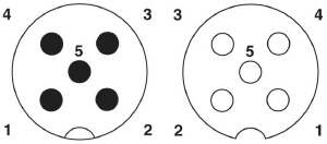
|  | IOLM 4-EIP Connecting the PowerThe following provides an installation and
configuration overview for the IOLM 4-EIP. IOLM 4-EIP provides dual M12 (A-coded) power connectors.
If you purchased cables from Pepperl+Fuchs Comtrol, Inc., you can refer to
web site for cabling information. Maximum EMC protection is provided by a low impedance connection between functional earth,
the grounding tabs, and protective earth. The following table contains power-related information about the power supply. ![[Note]](images/note.gif) | | Note |
|---|
Power connectors must have an approved cable or protective cover attached to the port guarantee IP67 compliance. |
|
| | Note |
|---|
† Us output available is determined by subtracting the following from the available input current.
IO-Link Mode module power Actual C/Q current for each IO-Link Master port Actual Vs current for each IO-Link port
IOLM 4-EIP requires a UL listed power supply with an output rating of 24VDC. |
|
You can use this procedure to connect the IOLM 4-EIP to a power supply. Securely attach the power cable between the male power connector and the power supply. Either attach a power cable between the female power connector and another device to
which you want to provide power or securely attach a connector cap to prevent dust or
liquids from getting into the connector. Apply the power and verify that the following LEDs are lit indicating that you are ready to begin configuration.
PWR MS, first the flashing green and red LEDs displays that it is in self-test mode.
After the self-test, depending on whether you set the IP address with the rotary switch one of the following occurs:
| | Note |
|---|
If the IOLM 4-EIP has U-Boot bootloader v1.25 or higher, the MS LED is lit during the power-on cycle. |
|
NET, first it flashes green and red indicating that it is in self-test mode.
After the self-test, depending on whether you set the IP address with the rotary switch one of the following occurs:
| | Note |
|---|
If the IOLM 4-EIP has U-Boot bootloader v1.25 or higher, the NS LED is lit during the power-on cycle. |
|
EIP 1/2 should be steady green indicating that the link is up if both connectors are connected.
See the Troubleshooting page for addition information about the IOLM 4-EIP LEDs.
| |


