
|  | IOLM 8-PNIO Connecting the PowerThe following provides an installation and
configuration overview for the IOLM 8-PNIO.
 ![[Note]](images/note.gif) | | Note |
|---|
Important!
To avoid possible damage, ensure that the power supply used with the IOLM 8-PNIO is powered off before connecting power cables. |
|
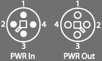
IOLM 8-PNIO provides dual M12 (T-coded) power connectors. If you purchased cables from Pepperl+Fuchs Comtrol, Inc., you can refer to
web site for cabling information. The following table contains power-related information about the power supply. | | Note |
|---|
Power connectors must have an approved cable or protective cover attached to the port guarantee IP67 compliance. |
|
| | Note |
|---|
† Vs output available is determined by subtracting the following from
the available input current.
IO-Link Mode module power Actual C/Q current for each IO-Link Master port Actual Vs current for each IO-Link port
†† VA output available is the same as the available Va input current |
|
You can use this procedure to connect the IOLM 8-PNIO to a power supply. Securely attach the power cable between the male power connector and the power supply. Either attach a power cable between the female power connector and another device to
which you want to provide power or securely attach a connector cap to prevent dust or
liquids from getting into the connector.
PWR - The LED is lit indicating that the IO-Link Master is
receiving power. MS - The MS LED is off, which means that the IOLM is operating as expected.
| | Note |
|---|
If the IOLM 8-PNIO has U-Boot bootloader v1.25 or higher, the MS LED is lit during the power-on cycle. |
|
NS - if the NS LED is off;
that means that there is no PLC connected. If the NS LED is lit and green, that
means that a PLC is connected.
| | Note |
|---|
If the IOLM 8-PNIO has U-Boot bootloader v1.25 or higher, the NS LED is lit during the power-on cycle. |
|
The Link LEDs should be steady green indicating that the link is up.
The ACT LED flashes to indicate network activity.
See the Troubleshooting page for addition information about the IOLM 8-PNIO LEDs.
| |


