|  | RocketLinx MP1204-XT Hardware InstallationYou can use the following information to install the MP1204-XT hardware.
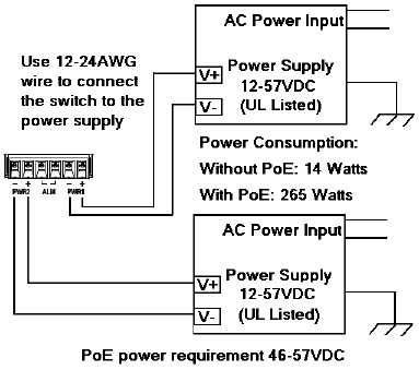
Use the following information to connect the DC power to the MP1204-XT. The MP1204-XT provides redundant power inputs (PWR 1/2), which supports reverse polarity protection, and accepts a positive or negative powersource (12V – 57V). However, PWR1 and PWR2 must apply to the same mode In addition, the MP1204-XT supports reverse polarity protection.
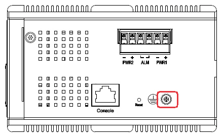
 If desired, connect the alarm relay output. The fault conditions can be defined using the MP1204-XT user interface or Command Line Interface (CLI) after you program the IP address. The relay output contacts are on the terminal block connector with the power on the MP1204-XT The relay contact supports up to 0.5A at 24VDC. Do not apply voltage and current higher than the specifications. The relay output is controlled by the pre-defined operating rules. To activate relay output function, refer to the RocketLinx MP1204-XT User Guide. 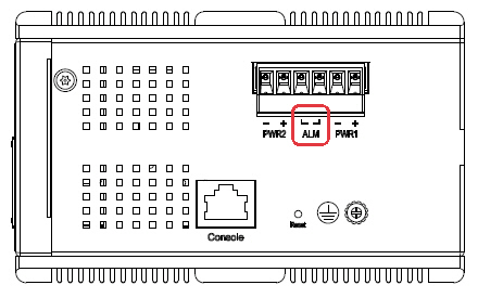 Connect a ground wire between the MP1204-XT chassis and earth ground using 12-24AWG wire to ensure that the MP1204-XT is not damaged by noise or electrical shock.
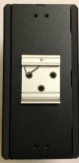
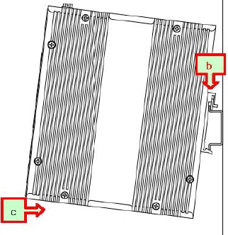
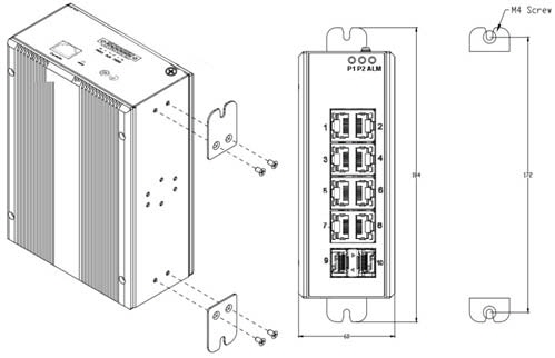
 Mount the MP1204-XT to the DIN rail using the clip on the back of the unit or use the wall mounting plate. Follow the steps below to install the MP1204-XT on a DIN rail: Follow the steps below to install the MP1204-XT with the wall mounting plate: Connect straight-through or cross-over Ethernet cables between the MP1204-XT RJ45 ports and the network nodes or powered devices (PDs) and connect SFPs. Ports 1-8 are Gigabit IEEE802.3af (PoE) and IEEE802.3at (PoE Plus) compliant Ethernet ports. The following table shows the RJ45 PoE pin-out assignment.
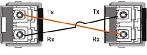
All of the fast Ethernet ports auto-detect the signal from connected devices to negotiate the link speed and duplex mode. Auto MDI/MDIX allows you to connect another switch, hub, or workstation without changing straight-through or crossover cables. Crossover cables cross-connect the transmit lines at each end to the received lines at the opposite end. Always make sure that the cables between the switch and attached devices (for example, switch, hub, or workstation) do not exceed 100 meters (328 feet). Optionally, connect the SFP transceivers. Cross-connect the transmit channel at each end to the receive channel at the opposite end . The MP1204-XT two Gigabit SFP ports are combo ports with the Gigabit Ethernet RJ45 ports. The speed of the SFP port supports 100BASE-FX and 1000BASE-X. The SFP ports accept standard mini-GBIC SFP transceivers. To ensure system reliability, Pepperl+Fuchs Comtrol, Inc. recommends using Pepperl+Fuchs Comtrol, Inc. certified SFP transceivers. The SFP and corresponding RJ45 ports work in an exclusive mode. Traffic sent or received through the SFP module will have priority thus no traffic will be sent or received over the corresponding RJ45 connection. To use the RJ45 connection, remove the corresponding SFP module.
The SFP port does not function until the fiber cable is linked to another active device. When the SFP module is plugged in and there is no active connection (link) on the fiber, then the Gigabit port will link.
Verify that the LEDs display that it is ready to configure the IP address.
|  | ||||||||||||||||||||||||||||||||||||||||||||||||||||||||||||||||||||||||||||||||||||||||||
 | 02/06/20 | Home | Comtrol Website |  | |
 | Copyright © 2020 Pepperl+Fuchs Comtrol, Inc. |  | ||
![[Note]](images/note.gif)

