
| RocketLinx ES8105 Series Installation OverviewUse the following overview to install the ES8105 series. All models are referred to as the ES8105 unless a procedure is specific to a specific model.
The ES8105 series provides reverse polarity protection and accepts a positive or negative power source. The recommended working voltage is 24VDC (18-32VDC) and a maximum power consumption of 4W.
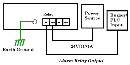
The ES8105 has a built-in alarm-relay for port link and power events notifications. The relay contacts are normally open and remain open when there is no failure event. The relay contacts will close when there is a failure event to notify. The failure events are selectable and enabled using the DIP switch on the ES8105.
The relay contacts are rated for a maximum of 1A at 24VDC.
Connect a ground wire between the chassis and earth ground using 12 to 24AWG wire to ensure that the ES8105 is not damaged by noise or electrical shock. If you are going to mount the ES8105 on a grounded DIN rail, you do not need to also connect the ground wire.
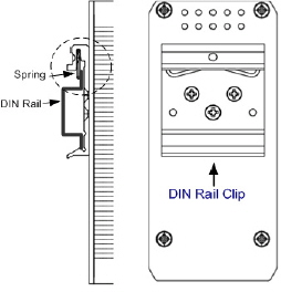
Use this table to set the DIP switch for the relay output alarm. Use these steps to mount the ES8105.
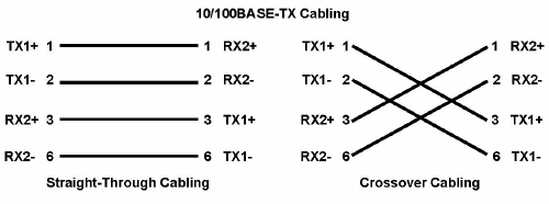
To remove the ES8105 from the track, reverse the steps above. Connect standard Ethernet cables between the ES8105 Ethernet ports and the network nodes. The Fast Ethernet ports support 10BASE-T and 100BASE-TX, full- or half-duplex modes. All of the Fast Ethernet ports automatically detect the signal from the connected devices to negotiate the link speed and duplex mode. Auto MDI/MDIX allows you to connect another switch, hub, or workstation without changing straight-through or crossover cables. Crossover cables cross-connect the transmit lines at each end to the received lines at the opposite end.
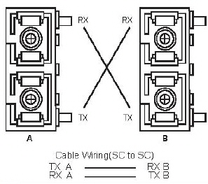
Always make sure that the cables between the switch and attached devices (for example, switch, hub, or workstation) do not exceed 100 meters (328 feet). If you are installing a ES8105F or ES8105F-XT, connect the fiber port. The fiber connector is a standard connector or square connector (SC).
A wrong connection will cause the fiber port not to work properly.
You can refer to this table for LED information.
| ||||||||||||||||||||||||||||||||||||


![[Note]](images/note.gif)


| 02/06/20 | Home | Comtrol Website | |||
| Copyright © 2020 Pepperl+Fuchs Comtrol, Inc. | ||||