|  | RocketLinx ES7110-VB Installation OverviewUse the following overview and documentation to install the ES7110-VB.
See the ES7110 Installation page, if you are installing an ES7110. Set the DIP switch to configure the Port Link Alarm.
The port link failure alarm is applicable when ES7110-VB ports are connected to
an auto-negotiation capable 10/100 full-duplex device.
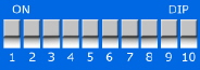
This table provides information about the DIP switch settings for the ES7110-VB.
Wire the earth ground.
To ensure the system is not damaged by noise or any electrical shock, we suggest that you to make an
exact connection between the ES7110-VB and earth ground. On the bottom side of the ES7110-VB,
there is one earth ground screw. Loosen the earth ground screw with a screw driver;
then tighten the screw after the earth ground wire (12 to 24AWG) is connected.
If you are going to mount the ES7110-VB on a grounded DIN rail, you do not need to also connect the ground wire. Wire the power inputs. The required output voltage is 12-24VDC, which delivers IEEE 802.3af PoE on all ports.
![[Note]](images/note.gif) | | Note |
|---|
Power should be disconnected from the power supply before connecting it to the ES7110-VB. Otherwise, your screwdriver
blade can inadvertently short your terminal connections to the grounded enclosure. |
|
Disconnect the terminal block from the ES7110-VB.
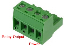 Insert the positive and negative wires (12 to 24 AWG)
into the V+ and V- contact on the terminal block connector. Tighten the wire-clamp screws to prevent the DC wires from becoming loose. Plug the terminal block into the ES7110-VB.
Insert the wires and set the DIP switch using the table (above).
After setting the DIP switch to ON, the relay output alarm will detect any
power or port failures, and form a short circuit. The alarm relay output is Normal Open.
If desired, mount the unit. Connect the appropriate Ethernet cables between the ES7110-VB
Ethernet ports and the network nodes.
Ports G1 and G2 are Gigabit Ethernet uplink ports that support 10BASE-T, 100BASE-TX, and 1000BASE-TX. Ports 1-8 are Fast Ethernet 10/100BASE-TX PoE ports that are IEEE 802.3af (PoE) compliant
(15.4W maximum).
All of the Ethernet ports auto-detect the signal from connected devices to negotiate the link speed and duplex mode.
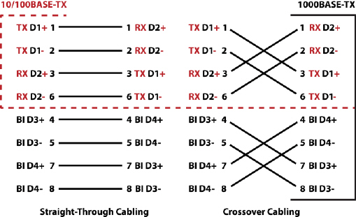
Auto MDI/MDIX allows you to connect another switch, hub, or workstation without changing straight-through or crossover cables.
Crossover cables cross-connect the transmit lines at each end to the received lines at the opposite end.
Always make sure that the cables between the switch and attached devices (for example, switch, hub, or workstation)
do not exceed 100 meters (328 feet).
10BASE-T: Category 3, 4, or 5 cable, 100BASE-TX: Category 5 cable 1000BASE-TX: Category 5 or 5e cable IEEE 802.3af: Category 5 or higher cable
| |