
|  | IOLM DR-8-EIP Connect the Power
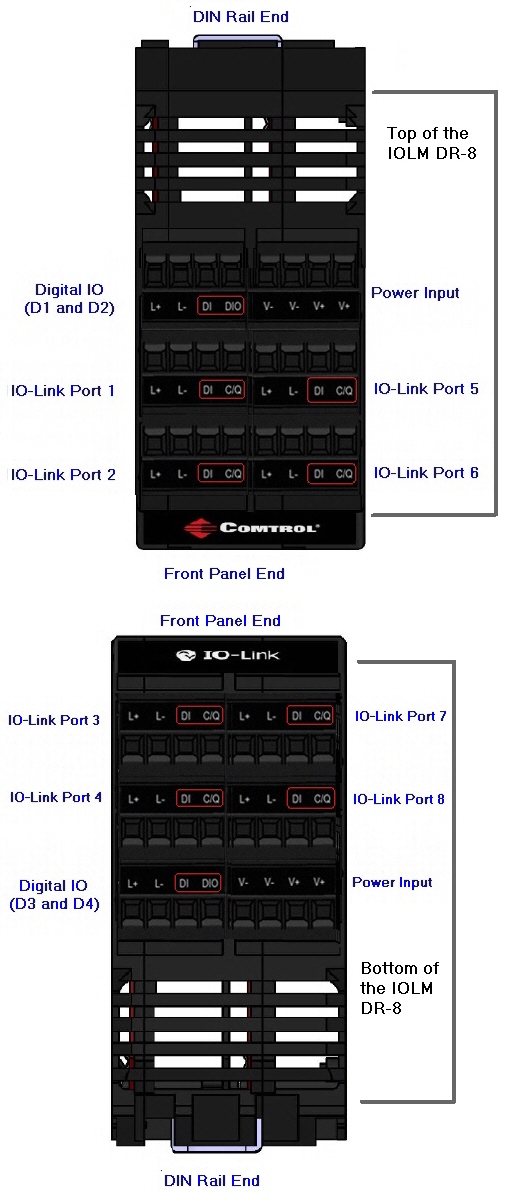
The IOLM DR-8-EIP provides two redundant power inputs with screw terminals on the top and bottom of the IOLM DR-8-EIP.
![[Note]](images/note.gif) | | Note |
|---|
Use either power terminals (top or bottom) but do not use both to supply power to the IOLM DR-8-EIP.
|
|
The following provides power information for the IOLM DR-8-EIP.
The following table provides signal information.
Power Supply Current and VoltageMaximum EMC protection is provided by a low impedance connection between functional earth,
the ground when connected to a ground DIN rail, and protective earth. The following table contains power-related information about the power supply.
| | Note |
|---|
The total supply of current for all connected IO-Link devices.
IOLM DR-8-EIP requires a UL listed power supply with an output rating of 24VDC. |
|
You can use this procedure to connect the IOLM DR-8-EIP to a power supply.
| | Note |
|---|
Power should be disconnected from the power supply before connecting it to the IOLM DR-8-EIP.
Otherwise, your screw driver blade can inadvertently short your terminal connections to the grounded enclosure. |
|
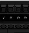
Insert positive and negative wires (12-24AWG) into the V+ and V- contacts.
You can refer to the port placement. Tighten the wire-clamp screws to prevent the wires from coming loose. Apply the power and verify that the following LEDs are lit indicating that you are ready to begin configuration.
PWR MS, first the flashing green and red LEDs displays that it is in self-test mode.
| | Note |
|---|
If the IOLM DR-8-EIP has U-Boot bootloader v1.25 or higher, the MS LED is lit during the power-on cycle. |
|
After the self-test, one of the following occurs:
NS, first it flashes green and red indicating that it is in self-test mode.
| | Note |
|---|
If the IOLM DR-8-EIP has U-Boot bootloader v1.25 or higher, the NS LED is lit during the power-on cycle. |
|
After the self-test, one of the following occurs:
The Link LEDs should be steady green indicating that the link is up.
The ACT LED flashes to indicate network activity.
You can refer to this image for information about your IOLM DR-8-EIP.
| |


