Connect the DC power to the ES7510-XT.
The ES7510-XT provides redundant or aggregated power inputs,
depending on the voltage of the power input.
If there are more than two power inputs connected with different voltages,
the ES7510-XT is powered from the highest connected voltage (redundant power).
If the voltages of power inputs are the same, the total power output is aggregated.
In addition, the ES7510-XT supports reverse polarity protection.
![[Note]](images/note.gif) | | Note |
|---|
|
Remember to unplug the power terminal block before making wire connections, otherwise the
screwdriver can inadvertently short the terminal connections to the grounded enclosure.
|
|
Insert the wires (12 - 24 AWG) from the power supply into the terminal block connector contacts.
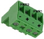
Tighten the wire-clamp screws to prevent the wires from coming loose.
The PWR1/PWR2 LED turns red during the boot cycle and turns green when the unit is ready.
If desired, connect the digital input (DI) and alarm relay output (DO). The fault conditions can be defined using the ES7510-XT
user interface (web page) or Command Line Interface (CLI).
The relay output (DO) and DI contacts are on the terminal block connector on the bottom of the ES7510-XT
The relay contact (DO) supports up to 0.5A at 24VDC. Do not apply voltage and current higher than
the specifications. The relay output (DO) is controlled by the pre-defined operating rules. To activate relay output
function, refer to the RocketLinx ES7510-XT User Guide.
The Digital Input (DI) accept one external DC type signal input and can be configured to
send alert message through Ethernet when the signal is changed.
The DI accepts DC type signal and supports isolated input circuit with digital high level input
11VDC to 30VDC and digital low level input 0VDC to 10VDC. Do not apply a higher voltage
than the specification; it may cause internal circuit damage or a cause an incorrect DI action.
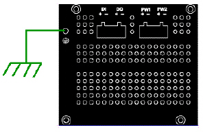 Connect a ground wire between the ES7510-XT chassis and
earth ground using 12-24AWG wire to ensure that the ES7510-XT is not damaged by noise or electrical shock.
Connect a ground wire between the ES7510-XT chassis and
earth ground using 12-24AWG wire to ensure that the ES7510-XT is not damaged by noise or electrical shock.
Loosen the earth ground screw on the right side of the ES7510-XT.
Tighten the screw after the earth ground wire is connected.
Connect a ground wire between the earth ground (surge) screw and earth ground to
provide enhanced surge and lighting immunity.
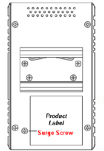
Loosen the earth ground screw located on the back of the unit next to the compliance label.
Tighten the screw after the ground wire is connected.
Make sure that you remove the surge ground screw before insulation/Hi-pot testing.
Mount the ES7510-XT to the DIN rail using the clip on the back of the unit or use the wall mounting plate.
Follow the steps below to install the ES7510-XT on a DIN rail:
If necessary, use the screws to attach DIN rail clip to the rear panel of the ES7510-XT.
(To remove DIN rail clip, reverse Step 1.)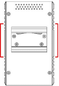
Insert the upper end of DIN rail clip into the back of DIN rail track from its upper side.
Lightly push the bottom of DIN rail clip into the track.
Verify that the DIN rail clip is tightly attached on the track.
To remove the ES7510-XT from the track, reverse the steps above.
Follow the steps below to install the ES7510-XT with the wall mounting plate:
To remove the DIN rail clip from the ES7510-XT, loosen the screws from the DIN rail clip.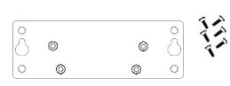
Place the wall mounting plate on the rear panel of the ES7510-XT.
Use the screws to attach the wall mounting plate to the ES7510-XT.
Use the hook holes at the corners of the wall mounting plate to hang the ES7510-XT onto the wall.
To remove the wall mounting plate, reverse the steps above.
Connect standard Ethernet cables between the ES7510-XT ports and the network nodes.
Ports 1-8 are 10/100BASE-TX IEEE802.3af (PoE) and IEEE802.3at (PoE Plus)
compliant Ethernet ports.
Ports G9 and G10 are Gigabit combo ports (RJ45/SFP) that support
10/100/1000BASE-TX, 100BASE-FX, and 1000BASE-X with digital diagnostic monitoring (DDM)
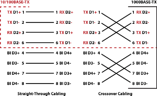
All of the fast Ethernet ports auto-detect the signal from connected devices
to negotiate the link speed and duplex mode. Auto MDI/MDIX allows you to connect another switch, hub, or
workstation without changing straight-through or crossover cables.
Crossover cables cross-connect the transmit lines at each end to the received lines at the opposite end.
Always make sure that the cables between the switch and attached devices (for example, switch, hub, or workstation)
do not exceed 100 meters (328 feet).
10BASE-T: Category 3, 4, or 5 cable
100BASE-TX: Category 5 cable
1000BASE-TX: Category 5 or 5e cable
IEEE 802.3af: Category 5 cable
IEEE 802.3at: Category 5e or 6 cable
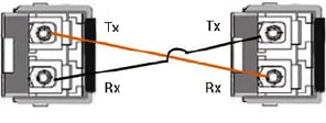
Optionally, connect the SFP transceivers.
Cross-connect the transmit channel at each end to the receive channel at the opposite end .
The ES7510-XT two Gigabit SFP ports are combo ports with the Gigabit Ethernet RJ45 ports.
The speed of the SFP port supports 100BASE-FX and 1000BASE-X. The SFP ports accept standard
mini-GBIC SFP transceivers. To ensure system reliability, Pepperl+Fuchs Comtrol, Inc. recommends using
Pepperl+Fuchs Comtrol, Inc.
certified SFP transceivers.
The SFP and corresponding RJ45 ports work in an exclusive mode.
Traffic sent or received through the SFP module will have priority thus no traffic will be sent
or received over the corresponding RJ45 connection. To use the RJ45
connection, remove the corresponding SFP module.
| | Note |
|---|
This is a Class 1 Laser/LED product. Do not stare at the Laser/LED Beam. |
|
The SFP port does not function until the fiber cable is linked to another active device.
When the SFP module is plugged in and there is no active connection (link) on the fiber, then the Gigabit port will link.
Plug the SFP transceiver into the SFP fiber transceiver.
Connect the transmit channel to the receive channel at each end.
Check the direction/angle of the fiber transceiver and the fiber cable.
Verify that the LEDs display that it is ready to configure the IP address.
The Link/Act LED is lit when the cable is correctly connected.
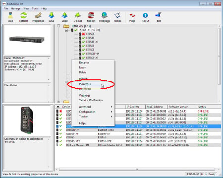
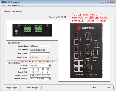
Configure the IP address using one of the following methods:
The easiest way to configure a static IP address for your network in the ES7510-XT is to use a
Windows host and PortVision DX (see Programming the IP Address).
For information about using other configuration methods,
refer to the RocketLinx RocketLinx ES7510-XT User Guide.