|  | RocketLinx ES9528-XT V2 Installation OverviewYou can use the following overviews to set up the RocketLinx ES9528-XT.
You can use this installation procedure and the
RocketLinx ES9528-XT User Guide,
which contains detailed installation and configuration information for the ES9528-XT.
Connect power to the ES9528-XT.
Mount the ES9528-XT into a rack.
Attach the brackets to the ES9528-XT by using the screws provided in the Rack Mount kit. Mount the ES9528-XT in the 19-inch rack by using four rack-mounting screws provided in the kit. When installing multiple switches, mount them in the rack one below the other.
Reserve 0.5U-1U of free space for multiple switches when installing in
high temperature environments. It is important to disperse the heat generated by the ES9528-XT.
![[Note]](images/note.gif) | | Note |
|---|
Temperature: Check if the rack environment temperature conforms to the specified operating temperature range.
Mechanical Loading: Do not place any equipment on top of the switch. In a high vibration environment,
additional rack mounting protection is necessary, like the flat board under/above the switch.
Grounding: Rack-mounted equipment should be properly grounded.
|
|
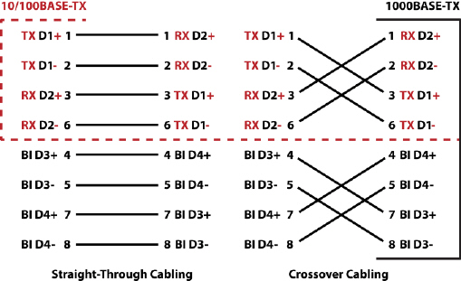
Connect standard Ethernet cables between the ES9528-XT Ethernet ports and the network nodes.
The Fast Ethernet ports (Ports 1-24) support 10BASE-T and 100BASE-TX,
full- or half-duplex modes. All of the Ethernet ports auto-detect the signal from connected devices
to negotiate the link speed and duplex mode. Auto MDI/MDIX allows you to connect another switch, hub, or
workstation without changing straight-through or crossover cables.
Crossover cables cross-connect the transmit lines at each end to the received lines at the opposite end.
Ports 25-28 are Gigabit (1000BASE-TX) Combo RJ45/SFP ports.
Always make sure that the cables between the switch and attached devices (for example, switch, hub, or workstation)
do not exceed 100 meters (328 feet).
10BASE-T: Category 3, 4, or 5 cable 100BASE-TX: Category 5 cable 1000BASE-TX: Category 5 or 5e cable
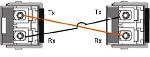
Optionally, connect SFP transceivers. Pepperl+Fuchs Comtrol, Inc. recommends using
Comtrol
certified SFP transceivers.
Cross-connect the transmit channel at each end to the receive channel at the opposite end .
The SFP port does not function until the fiber cable is linked to another active device.
When the SFP module is plugged in and there is no active connection (link) on the fiber, then
the Gigabit port will link.
The SFP and corresponding RJ45 ports work in an exclusive mode.
Traffic sent or received through the SFP module will have priority thus no traffic will be sent
or received over the corresponding RJ45 connection. To use the RJ45
connection, remove the corresponding SFP module.
| | Note |
|---|
This is a Class 1 Laser/LED product. Do not stare at the Laser/LED Beam. |
|
The SFP port does not function until the fiber cable is linked to another active device.
When the SFP module is plugged in and there is no active connection (link) on the fiber, then the Gigabit port will link.
Plug the SFP transceiver into the SFP fiber transceiver. Connect the transmit channel to the receive channel at each end. Check the direction/angle of the fiber transceiver and the fiber cable.
Verify that the LEDs display that it is ready to configure the IP address.
The Link/Act LED is lit when the cable is correctly connected.
Configure the IP address using one of the following methods:
The easiest way to configure a static IP address for your network in the ES9528-XT is to use a
Windows host and PortVision DX (see Programming the IP Address).
For information about using other configuration methods,
refer to the RocketLinx ES9528-XT User Guide.
Programming the IP AddressThe following procedure uses PortVision DX to program an IP address. Other network configuration methods are discussed in
the RocketLinx ES9528-XT User Guide.
Install PortVision DX
on a host system with a Windows operating system.
If you need assistance using PortVision DX, see the help system or the
PortVision DX User Guide. Start PortVision DX. PortVision DX can be started from
Start --> All Programs --> Comtrol --> PortVision DX. Click the Scan button. Select the Pepperl+Fuchs Comtrol, Inc. product families that you want to locate and
click the Scan button.
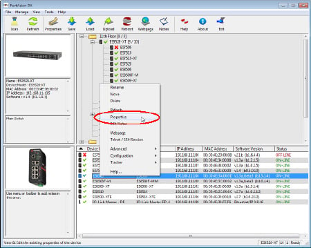
Configure the ES9528-XT IP address for your network.
Right-click the ES9528-XT in the Device List (lower)
or Device Tree (upper) pane that you want to configure and click Properties.
Enter a user-friendly Device Name, which displays a friendly device
name on the main page.
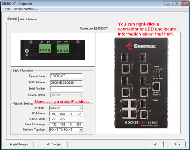 Optionally, enter the ES9528-XT serial number. Select the appropriate IP Mode for your environment. If you select Static IP:
Enter an appropriate IP Address for this ES9528-XT. Enter an appropriate Subnet Mask address for your network. Enter an appropriate Gateway address for your network.
Optionally, select the appropriate Network Topology, which is an informational field. Click the Apply Changes button. Click Close to return to the main screen.
You are now ready to configure the ES9528-XT features.
Configuring ES9528-XT FeaturesThe ES9528-XT provides both in-band and out-band configuration methods:
Out-band management means that you configure the ES9528-XT using the RS-232 console cable and the
Command Line Interface (CLI) to access the ES9528-XT without attaching an admin PC to the network.
You can also use out-band management, if you lose the network connection to the ES9528-XT. In-band management means that you connect remotely using the ES9528-XT IP address through the network.
You can remotely connect with the ES9528-XT Java applet web interface or a Telnet console and the CLI.
The following procedure uses a web browser to configure ES9528-XT features.
Refer to the RocketLinx ES9528-XT User Guide
for other configuration methods.
If necessary, install the latest version of the
Java Runtime Environment,
which is required to run the web management interface. Open a web browser and enter the IP address of the ES9528-XT. Click Run when Java prompts you to run the applet. Enter admin for both the user name and the password when prompted. Use the web interface to configure your device as needed for your network.
You can refer to the ES9528-XT documentation library for additional information.
| |