
| RocketLinx ES7206-XT Installation OverviewYou can use the following overview to install the ES7206-XT.
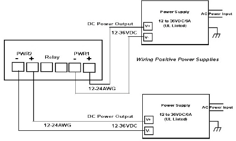
The ES7206-XT provides redundant power, reverse polarity protection, over-current protection and accepts a positive or negative power source but PWR1 and PWR2 must be applied with power sources of same polarity. The terminal block accepts 12 - 24AWG wire. Use a UL listed power supply with the required output voltage of 12-36VDC to deliver IEEE 802.3at PoE Plus on all PoE ports (Ports 1-4). The power supply must be rated as follows:
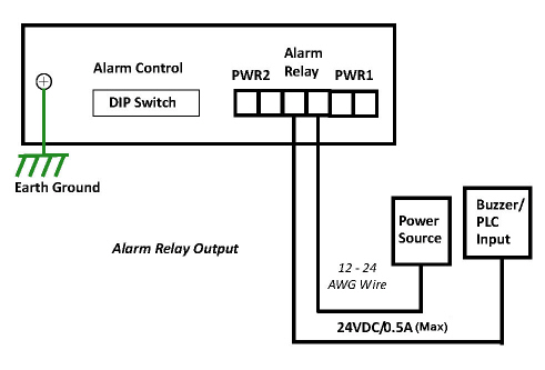
To ensure the system is not damaged by noise or any electrical shock, we suggest that you to make an exact connection between the ES7206-XT and earth ground. On the bottom side of the ES7206-XT, there is one earth ground screw. Loosen the earth ground screw with a screw driver; then tighten the screw after the earth ground wire (12 to 24AWG) is connected. If you are going to mount the ES7206-XT on a grounded DIN rail, you do not need to also connect the ground wire. The alarm relay output or digital output (DO) contacts are on the terminal block connector. The alarm relay output contacts are normally open. The alarm relay output contacts close when the alarm is enabled with the DIP switches and there is a port link failure or PoE failure on a port. The relay contact supports up to 0.5A at 24VDC. Do not apply voltage and current higher than the specifications. Insert the wires and set the DIP switch.
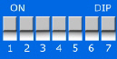
The ES7206-XT has an 8-pin DIP switch located on the bottom panel to configure the Port Link Alarm for the Ethernet ports. The following table shows the DIP switch number mapping to the corresponding options.
This table provides information about the DIP switch settings for the ES7206-XT. The ES7206-XT can be mounted on a DIN rail. The DIN rail clip is already attached to the ES7206-XT at the factory.
Connect one end of an Ethernet cable into the Ethernet port of the ES7206-XT and the other end to the attached networking device:
All of the Ethernet ports auto-detect the signal from connected devices to negotiate the link speed and duplex mode. Auto MDI/MDIX allows you to connect another switch, hub, or workstation without changing straight-through or crossover cables. Crossover cables cross-connect the transmit lines at each end to the received lines at the opposite end.
Always make sure that the cables between the switch and attached devices (for example, switch, hub, or workstation) do not exceed 100 meters (328 feet) and are Category 5e or higher cable. You can connect an SFP transceiver to Port 6. Pepperl+Fuchs Comtrol, Inc. recommends using approved SFP transceivers. Cross-connect the transmit channel at each end to the receive channel at the opposite end as illustrated in the figure. Make sure that you use an SFP fiber transceiver compliant with UL certification and EN60825 Class 1. For ensure system reliability, Pepperl+Fuchs Comtrol, Inc. recommends using Pepperl+Fuchs Comtrol, Inc. certified Gigabit SFPs. Connect the SFP transceiver by plugging the cable into SFP fiber transceiver fist. Cross‐connect the transmit channel at each end to the receive channel at the opposite end as illustrated in the figure. 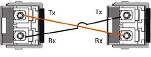 You can this table for information about the LEDs. 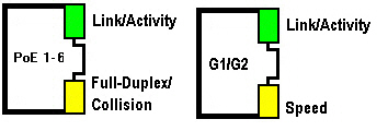
| |||||||||||||||||||||||||||||||||||||||||||||||||||||||||||||||||||||||||||


![[Note]](images/note.gif)
| 02/06/20 | Home | Comtrol Website | |||
| Copyright © 2020 Pepperl+Fuchs Comtrol, Inc. | ||||